Drafting in Modern Industry Why Precision Blueprints Power Architecture Aerospace and Design

A great building, aircraft component, circuit board, or bridge rarely begins as a finished object. It begins as an idea that must survive measurement, materials, safety checks, budget limits, and real-world use. Drafting is the discipline that carries that idea across the gap.
At its best, drafting is both technical and creative. It turns sketches, concepts, and design intentions into precise drawings that other people can read, test, price, approve, and build. A line on a blueprint may represent a wall, a welded joint, a duct route, a circuit trace, or a machined part. If that line is unclear, the whole project can drift.
That is why drafting remains essential across modern industry. Even as tools have moved from manual boards to CAD software, 3D modeling, and cloud-based collaboration, the core purpose has not changed: make the idea buildable.

Drafting turns creative concepts into precise plans
Design often starts with a question: What should this structure do? How should this part perform? Where should power, water, air, or data move? The first answers may be rough sketches or verbal descriptions. Drafting gives those answers structure.
A technical drawing defines shape, size, location, material, connections, and assembly requirements. It shows not only what something looks like, but how it should be made. That difference matters. A concept image may inspire interest. A draft can guide construction, machining, inspection, permitting, and maintenance.
Drafting also controls ambiguity. A designer might picture a sleek facade, a lightweight bracket, or a compact control panel. Engineers, fabricators, electricians, inspectors, and contractors need more than a picture. They need dimensions, tolerances, notes, symbols, and standards.
A clear drawing answers practical questions such as:
How wide is the opening?
What material is specified?
Where does this part connect?
What clearance is required?
Which code or standard applies?
What changes from the previous revision?
This is where the art of drafting shows itself. Good drawings are not cluttered. They do not show every possible detail at once. They reveal the right information at the right scale, with enough context for each person using the plan.
Why precision is the difference between concept and construction
Precision is the foundation of drafting. In industries where parts must fit, loads must transfer, and systems must work safely, small errors can become expensive problems.
A cabinet that is off by a fraction of an inch may be annoying. A steel connection, aircraft component, or printed circuit board that is off by the same amount can cause failure, delay, or redesign. Drafting reduces this risk by defining measurements in a controlled way.
Precision in measurements is more than putting numbers on a page. It includes:
Scale
Units
Tolerances
Centerlines
Datums
Reference points
Clearances
Section views
Dimension chains
In manufacturing, tolerances tell a machinist how much variation is acceptable. In architecture, dimensions guide the placement of walls, doors, windows, stairs, fixtures, and structural elements. In electronics, tiny layout choices affect signal paths, heat, and component placement.
Precision also supports cost control. When teams understand exact quantities and dimensions, they can estimate materials more accurately. They can order the right components, reduce waste, and avoid field changes that slow the work.
A drawing is not just a picture of the final product. It is a contract between design intent and physical reality.
Drafting creates a common language for technical teams
Modern projects rarely belong to one person. Architects work with structural, mechanical, electrical, and plumbing engineers. Aerospace designers pass drawings between stress analysts, machinists, quality teams, and assembly crews. Electronics designers coordinate with enclosure designers, firmware teams, manufacturers, and testing labs.
Drafting gives these groups a common language.
A well-prepared drawing uses recognized symbols, line weights, notes, views, and naming conventions. This lets different specialists understand the same plan without guessing. For example, an electrical plan can show outlet locations, panel schedules, conduit routes, and equipment loads. A civil drawing can show grading, drainage, pavement sections, and utility connections. An architectural plan can show room layouts, wall types, door swings, accessibility clearances, and finish information.
This shared technical language is especially important when responsibilities overlap. A mechanical duct may need to pass through a structural bay. A cable tray may share space with plumbing. A window detail may affect energy performance, weatherproofing, and structural loads. Drafting helps teams identify these relationships before construction or fabrication begins.
Clear drawings also make revisions traceable. When a plan changes, teams need to know what changed, why it changed, and which version is current. Revision clouds, notes, issue dates, and coordinated sheet sets reduce confusion and help everyone build from the same information.

Architecture depends on drawings that satisfy design and code
Architecture may be the most familiar home of drafting. Floor plans, elevations, sections, site plans, reflected ceiling plans, and construction details all help turn a building idea into a coordinated set of instructions.
Architectural drafting balances beauty, function, structure, safety, and legal requirements. A plan must communicate the design clearly, but it must also show that the building can be used safely and built correctly.
Compliance with building codes is a major reason drafting matters. In the United States, building projects often need to meet local codes based on widely used model codes, along with zoning rules, energy codes, accessibility requirements, fire safety standards, and structural criteria. Drawings help reviewers confirm that a building meets those requirements.
Drafting supports code review by showing items such as:
Means of egress
Fire-rated assemblies
Stair dimensions
Accessibility clearances
Occupancy classifications
Structural systems
Energy-related assemblies
Plumbing fixture counts
Site access and setbacks
During construction, architectural drawings guide trades in the field. They help frame walls, place openings, install equipment, coordinate finishes, and resolve details. A good drawing set does not remove every possible question, but it reduces uncertainty and gives teams a reliable base for decisions.
Aerospace drafting leaves little room for assumption
Aerospace design demands extreme attention to detail. Aircraft and spacecraft rely on parts that must be strong, light, inspectable, and repeatable. A bracket, fastener pattern, panel, or duct component may look simple, but its drawing can carry critical information about materials, surface finish, heat treatment, hole tolerances, inspection points, and assembly sequence.
In aerospace, drafting supports safety and traceability. Every part needs a defined geometry. Every change needs control. Every assembly must fit with other systems inside limited space.
This is where drafting works closely with analysis. Engineers may test a design virtually before a part is built. They can check stress, airflow, vibration, thermal behavior, and interference with nearby components. The drawing then becomes part of a feedback loop. If testing shows a weak point or clearance problem, the design changes and the drawing updates.
Problem-solving through virtual testing helps reduce physical prototypes, although it does not replace real-world validation. It lets teams catch many design issues earlier, when changes cost less and cause less disruption.
Electronics drafting makes invisible systems buildable
Electronics may seem far from blueprints, but it relies heavily on drafting principles. Circuit diagrams, printed circuit board layouts, wiring schematics, harness drawings, and enclosure drawings all translate electrical intent into a manufactured product.
In electrical design, a schematic shows how components connect. A board layout shows where those components sit and how copper traces route between them. A wiring drawing shows cable paths, connectors, pin assignments, and labels. These drawings help engineers, assemblers, inspectors, and repair technicians understand the system.
Good electronics drafting considers:
Component placement
Trace width and spacing
Heat-producing parts
Connector access
Grounding
Signal paths
Manufacturing limits
Service and repair needs
In building projects, electrical drafting connects power distribution to physical space. Plans show panels, outlets, lighting, switches, emergency systems, equipment feeds, and low-voltage routes. These drawings must coordinate with architectural layouts, structural elements, mechanical systems, and code requirements.
Without sound drafting, electrical design becomes guesswork. With it, systems can be installed, tested, maintained, and expanded with much less risk.

Manufacturing uses drafting to control repeatability
Manufacturing depends on repeatable instructions. A single prototype can be adjusted by hand. A production run cannot rely on memory, guesswork, or personal preference. Drafting provides the data needed to make the same part again and again.
Mechanical drawings define geometry, dimensions, fits, tolerances, finishes, materials, and assembly relationships. They may include exploded views, section cuts, bill of materials references, weld symbols, machining notes, and inspection requirements.
This matters across many manufacturing processes, including:
CNC machining
Sheet metal fabrication
Injection molding
Welding
Casting
Additive manufacturing
Assembly line production
A machinist needs exact dimensions and tolerances. A welder needs joint details and symbols. A quality inspector needs measurable criteria. A purchasing team needs material specifications. Drafting ties these needs together.
Digital models have changed manufacturing, but they have not made drafting obsolete. Many shops use model-based definitions, 2D drawings, or both. The key is still the same: define the product clearly enough that it can be made, inspected, and approved.
Civil engineering drafting shapes the built environment
Civil engineering drafting helps create roads, bridges, drainage systems, utilities, subdivisions, rail corridors, and public infrastructure. These projects must fit into existing land, weather patterns, regulations, and community needs.
Civil drawings often include site plans, grading plans, profiles, cross sections, utility layouts, erosion control plans, stormwater details, and construction notes. They show how a project interacts with terrain and nearby systems.
A grading plan, for example, does more than show slopes. It affects water flow, building access, pavement performance, and long-term maintenance. A utility plan must avoid conflicts between water, sewer, gas, electric, and communications lines. A road profile must consider drainage, sight distance, earthwork, and safety.
Civil drafting is also central to permitting. Reviewers need drawings that document boundaries, easements, stormwater management, traffic impacts, and environmental controls. Construction crews need plans that can guide work over large areas, often with many moving parts.
Digital drafting has changed the speed and scope of collaboration
Manual drafting required remarkable skill. Drafting boards, T-squares, triangles, compasses, lettering guides, and ink pens produced drawings that were both functional and often beautiful. That craft still informs good drawing practice.
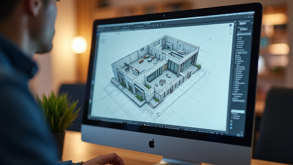
Digital tools have changed how drafting happens. CAD software allows designers to draw, edit, dimension, and revise with far greater speed. 3D modeling lets teams see form, fit, and conflicts before fabrication or construction. Cloud sharing keeps drawings available to teams in different locations and helps reduce version confusion.
Modern drafting tools support:
2D drawings for plans, sections, and details
3D models for spatial coordination
Parametric parts that update when dimensions change
Clash checks between building systems
Digital markups and revision tracking
Shared files for remote teams
Export formats for fabrication equipment
The shift to digital drafting has also changed expectations. Teams now expect faster revisions, clearer coordination, and better access to current drawings. A contractor in the field may review a model on a tablet. A manufacturer may pull geometry straight from a digital file. An engineer may mark up a design from another state.
Still, software does not replace judgment. A poor drawing made in a powerful program is still a poor drawing. Good drafting requires technical knowledge, spatial thinking, attention to detail, and respect for the people who must build from the plan.
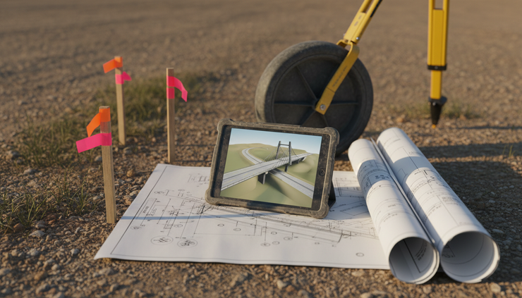
The future of drafting is digital, but the purpose is timeless
Drafting has moved from hand-drawn blueprints to CAD files, 3D models, and shared cloud platforms. The tools will keep changing. More teams will use model-based workflows, digital twins, automated checks, and connected project files. That progress will make drawings faster to revise and easier to share.
Yet the reason drafting matters has not changed. It brings discipline to imagination. It helps architects shape buildings, aerospace teams refine complex parts, electronics designers lay out reliable systems, manufacturers repeat work accurately, and civil engineers build infrastructure that fits the world around it.
A precise blueprint is more than documentation. It is a working agreement between idea, analysis, material, code, craft, and construction. When drafting is done well, creativity does not get lost in the details. It becomes buildable.


Comments